15 Common Injection Moulding Defects With Detailed Photos and Description
Here’s a realistic breakdown of common injection moulding defects, including detailed descriptions and visual characteristics (these actual pictures were embedded, descriptions will be vivid):
1. Short Shot (Incomplete Fill)
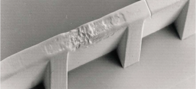
- Visual: Part is visibly incomplete. Material hasn’t filled the entire cavity. Missing features, thin sections absent, or the end of flow path is blunt/unformed. Edges of the short area are usually smooth but abruptly end. Common in thin sections or farthest points from the gate.
- Details:
- Causes: Insufficient material injected, low melt temperature (increased viscosity), injection speed/pressure too low, blocked/nozzle/runner/gate, venting inadequate (trapped air prevents fill), excessive clamp force (flashing prematurely).
- Severity: Critical. Part is unusable.
- Realism: Often looks like the plastic “ran out of steam.” You might see flow marks leading up to the unfilled area.
2. Sink Marks
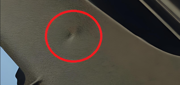
- Visual: Localized depression or dimple on the surface, typically directly over thicker sections (like ribs, bosses, or heavy cross-sections) or sometimes opposite the gate.
- Details:
- Causes: Insufficient cooling time/pack pressure, excessive material temperature, inadequate material in cavity (due to shrinkage). The thick section cools slower, shrinking inward and pulling the surface down.
- Severity: Cosmetic to Functional (if severe, affects dimensional accuracy or surface integrity).
- Realism: Can be subtle dips or pronounced craters. More common with semicrystalline materials (PP, PA) than amorphous (PC, PS). Feels like a smooth dent.
3. Flash (Burrs)
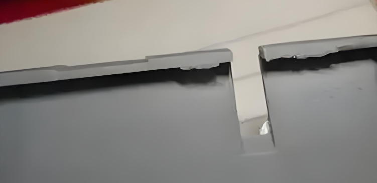
- Visual: Thin, unwanted layer of plastic protruding from the part edge, along the parting line (mould seam), around ejector pins, or through vent paths. Looks like excess “spillage.”
- Details:
- Causes: Excessive injection pressure/clamp force too low, mould wear or damage (misaligned, damaged shut-off surfaces), excessive melt temperature (material too fluid), contamination preventing mould closure, over-packing.
- Severity: Cosmetic (requires trimming) to Critical (prevents assembly, creates safety hazards – sharp edges).
- Realism: Can be paper-thin and fragile or thick and tough. Often requires manual trimming, adding cost. Sharp edges are a common safety issue.
4. Warpage (Distortion)

- Visual: Part is twisted, bent, bowed, or otherwise deformed from its intended shape after ejection and cooling. May not fit fixtures or assemblies.
- Details:
- Causes: Non-uniform cooling (different cooling rates/thicknesses), unbalanced flow leading to differential shrinkage, residual stresses from high injection pressure/packing, insufficient cooling time, poor part design (sharp transitions, unbalanced walls).
- Severity: Functional (part doesn’t fit/function) to Cosmetic. Often requires scrapping.
- Realism: Can be subtle (slight bow) or severe (part unusable). Often becomes apparent only after full cooling or during assembly attempts.
5. Weld Lines (Knit Lines)
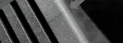
- Visual: A visible line, groove, or discoloration on the surface where two flow fronts meet and fuse. Strength along this line is often compromised.
- Details:
- Causes: Flow fronts meeting head-on (poor gate placement), flowing around holes/inserts, multiple gates. Low melt temp, slow injection speed, or contaminated material weaken the weld.
- Severity: Cosmetic to Critical (structural weakness). Weakest point in the part.
- Realism: Can be a faint hairline or a deep notch. Colour differences (whitish line) are common. Often feels like a slight ridge or groove. Easily snaps along this line.
6. Flow Lines (Flow Marks)

- Visual: Wavy patterns, streaks, or bands of slightly different colour/shine on the surface, usually in the direction of material flow. Different from weld lines.
- Details:
- Causes: Variations in flow speed, cooling near the mould wall while core flows, material viscosity changes, injection speed too slow, melt temp too low. Often involves fountain flow effect freezing unevenly.
- Severity: Primarily cosmetic. Rarely affects strength.
- Realism: Looks like faint “tiger stripes” or ripples. More noticeable on glossy parts or with pigmented materials.
7. Jetting
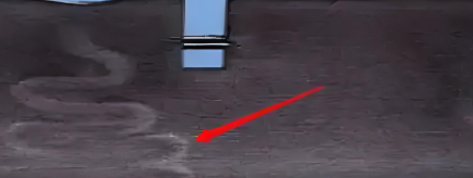
- Visual: A snake-like or worm-like trail of material starting from the gate, embedded into or sitting on the surface. Looks like the plastic “shot” into the cavity without adhering to the wall.
- Details:
- Causes: High injection speed through a small gate (material squirts like a fountain), gate design (directly impinging a core or wall), low melt or mould temperature. Material cools too fast mid-stream.
- Severity: Cosmetic to Structural (weak point, surface defect).
- Realism: Distinct, irregular, folded strand appearance, often discoloured. Feels like a raised ridge or embedded string.
8. Burn Marks (Diesel Effect)

- Visual: Black, brown, or rust-coloured discoloration, usually at the end of flow, trapped air areas, or near vents. Surface can be charred or degraded.
- Details:
- Causes: Trapped air compresses and overheats (diesel effect), degrading the plastic. Excessive melt temperature, injection speed too high (trapping air), poor venting, contaminated material (degradation).
- Severity: Cosmetic to Critical (material degradation weakens part).
- Realism: Appears scorched. Surface texture might be rougher or blistered. Often has a burnt smell.
9. Voids (Bubbles, Air Pockets)
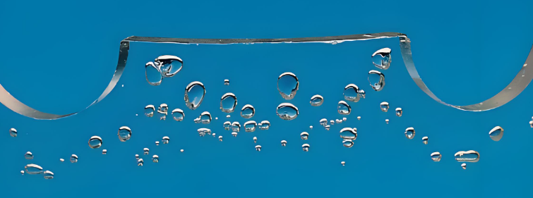
- Visual: Internal air pockets. Visible as bubbles within thick sections when backlit or sectioned. Surface Bubbles (Blistering) are raised bumps where gas expanded against the skin.
- Details:
- Causes: Shrinkage pulling material away from center in thick sections (internal voids), trapped air/moisture volatiles (surface/internal), insufficient pack pressure. Moisture in resin is a common culprit.
- Severity: Cosmetic (surface bubbles) to Functional (internal voids reduce structural integrity, act as stress concentrators).
- Realism: Internal voids are invisible externally; require X-ray or destructive testing. Surface bubbles look like small blisters. Parts might sound hollow when tapped.
10. Delamination (Lamination)
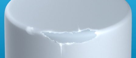
- Visual: A flaky surface layer or sheets peeling away from the main body. Looks like the plastic separated into distinct layers.
- Details:
- Causes: Contamination (incompatible materials, moisture, release agents), excessive use of mold release, poor material mixing, very low melt temperature. Layers fail to bond properly.
- Severity: Cosmetic to Critical (loss of strength, barrier properties).
- Realism: Surface appears cracked or flaky. You can often peel thin layers off with a fingernail or blade. Feels rough and layered.
11. Brittleness (Degradation)
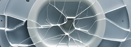
- Visual: Part fractures easily with little deformation, exhibiting a clean break. Colour might be off (yellowed, darkened).
- Details:
- Causes: Material degradation due to excessive melt temperature, excessive residence time in barrel, moisture in hygroscopic resins (hydrolysis), wrong material, high levels of regrind.
- Severity: Critical. Part fails under intended load.
- Realism: Break is often crystalline-looking (for semicrystalline materials) or very smooth/glassy. Part snaps instead of bends. Smells burnt or acrid when broken.
12. Silver Streaks (Splay)
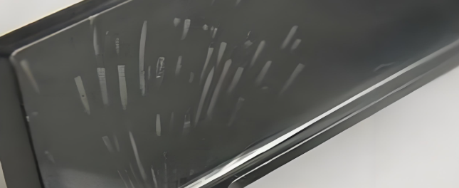
- Visual: Silvery, shiny streaks or splays radiating outwards, usually from the gate or along flow paths. Looks like tiny feathers or lightning bolts.
- Details:
- Causes: Moisture or volatiles (gas, degraded material, lubricant) vaporizing during injection and being stretched along the flow front. Poor drying, contaminated material, excessive melt temp, shear heating.
- Severity: Cosmetic to Functional (indicates contamination/degradation).
- Realism: Shiny, reflective streaks embedded just below or on the surface. Can be mistaken for flow lines but are distinctly metallic/silvery.
13. Discoloration

- Visual: Uneven colour, streaks, yellowing, browning, or fading compared to the intended colour. Can be localized or overall.
- Details:
- Causes: Material degradation (excessive heat, shear, residence time), contaminated material (wrong pigment, dirty barrel/mould), poor mixing, mould release interference, inadequate drying (moisture causes hazing).
- Severity: Cosmetic.
- Realism: Often appears as non-uniform colour patches, yellow/brown streaks, or a general “dirty” look compared to the standard.
14. Ejector Pin Marks

- Visual: Depression (sink) or protrusion (push mark) on the part surface where ejector pins pushed it out of the mould. Can be surrounded by stress whitening.
- Details:
- Causes: Insufficient cooling (part too soft when ejected), excessive ejection force/speed, insufficient draft angle, pin design/placement. Stress whitening indicates localized over-stressing.
- Severity: Cosmetic to Functional (if it affects dimensions or surface integrity).
- Realism: Circular or rectangular marks (matching pin shape) on the non-cosmetic side. Can be a slight dimple or a raised bump. Stress whitening looks like a white halo.
15. Gate Blush (Halo)
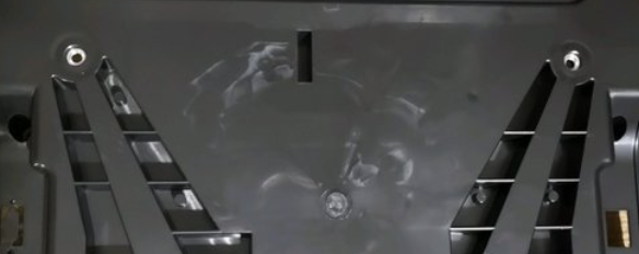
- Visual: A cloudy, hazy, or discolored ring or area surrounding the gate on the part surface.
- Details:
- Causes: High shear stress and/or rapid cooling at the gate as material flows through the constriction. Low melt temp, high injection speed, small gate size. Material experiences shear-induced crystallization or degradation.
- Severity: Primarily cosmetic.
- Realism: A distinct halo or rough patch centered on the gate location. Looks different from the surrounding polished surface.
Understanding these defects, their causes, and their visual signatures is crucial for troubleshooting and optimizing the injection moulding process for quality and efficiency. Root cause analysis often involves examining the defect location, material behaviour, and process parameters.

 Plastic Mold Design